
Sunday, July 22, 2012
Made it to Oshkosh
Made it to Airventure 2012! Got the camper set up and now looking forward to spending the next few days here and then on to New Space 2012. Speaking of, found out last night that my hotel reservation for New Space didn't go through so now I'm scrambling to make arrangements for that...c'est la vie.
Saturday, July 21, 2012
Frame assembly
Today I assembled the frame of the the MendelMax derivative I'm going to be using as my intermediate printer. The assembly was straight forward, although I did have some issues with the quality of my printed parts, not so much that it really prevented me from moving forward, but did in some cases require some fitting.
It's worthy to note that the recommended dimensions for the extrusions for this design are 420mm, 340mm, and 300mm. For my machine I scaled the design by 200mm in all axes. (so 620mm, 540, and 500 respectively) I will from here on out be referring to the longest extrusions as A, the middle as B, and the shortest as C. I purchased my extrusions from Misumi, which I have been highly impressed by so far.
If you are going to be building a MendelMax I would highly recommend either starting with a stock size printer or a more mild scaling. The rather large scaling I'm pursuing is because for the fiber winder and next printer I will be making I need a rather large build envelope. This is almost certainly going to cause problems, especially in the Y axis and build table. Unless you have a specific reason to go big, do yourself a favor and stick with the stock dimensions.
The first step of the build is to tap the center hole of the extrusions with an M5 tap. Tap all 4 of the B and C extrusions. It would be a good idea to start by taping the A extrusions since they don't actually need to be threaded and if you haven't manually tapped something before this will be good practice where it doesn't matter.
The next step is to drill four tool access holes in two of the A extrusions that will form the top cross bars. If you have the printed jig that is included in the design on Thingiverse use that. If not the center holes are 70mm from the end of the extrusion. My printed parts didn't include the jig so I had to do my best with calipers. I then used a friends drill press to drill the holes using a 1/4" drill bit.
 The next step is to thread in Misumi blind joint screws in four of the B extrusions that have been tapped.
 Now slide the joint screw into the slot of one of the A extrusions and slide it on until it aligns with the tool access hole. Tighten to secure, repeat on the other side, and then with the second drilled A extrusion.
 Not because I didn't have the printed jig for my tool access holes I was concern about this assembly being dimensionally correct. I used calipers to verify I had exactly 60mm of overhand on the top bar. If you used the printed jig this might not be strictly necessary but it couldn't hurt.
 My next step in assembly was attaching the top brackets. Slide four T slot nuts onto the A extrusion and two onto each of the B extrusions. Align the printed brackets, and secure with an M5 screw and washer. Repeat on the other blind jointed frame set.

At this point you should have to completed sub-frames that look like this.
 The next step is to add the lower frame vertices. In the case of my printed parts, they included one piece lower vertices which I'm unsure if I would recommend or not. The first step was to trap one T slot nut on the face of each of the B extrusions which already has the bracket on it. Also trap two additional T slot nuts on the faces of the B extrusion facing outward. (towards the overhang) Once the T slot nuts have been trapped attach the lower vertices to the tapped bottom of the B extrusions using one of the longer M5 screws and washer. (see full BOM for specific hardware, it's late and I can't recall what I used at the moment) Once the frame vertices have been attached via the threaded bottom secure the trapped T slot nuts to the vertices through the holes in the printed parts to completely secure the vertices.

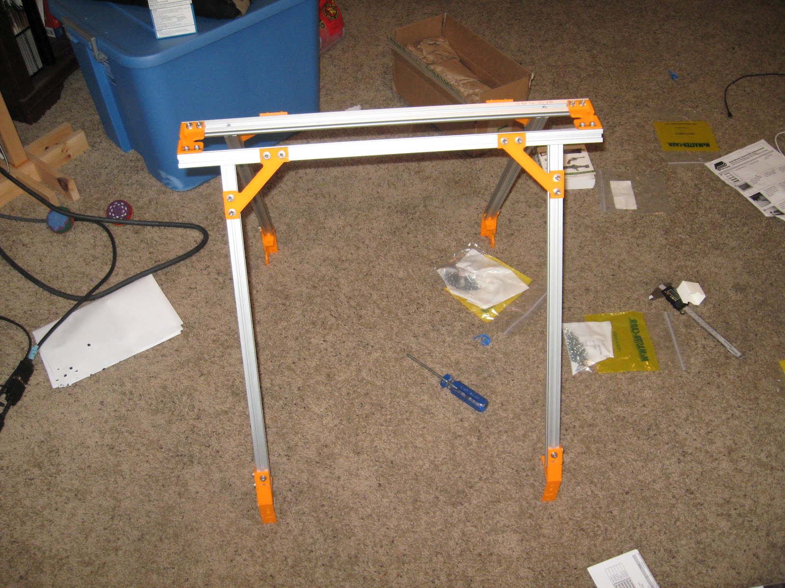
 The next step is to attach the two sub-assemblies that have been assembled so far using the Z top vertex. To do this on each side of each of the drilled A extrusions slide on two T slot nuts on the top slot, and one on the inward facing slot. Then align the Z top vertex onto the A extrusion, align the T slot nuts to the part and secure with a screw and washer. Repeat on other side of the A extrusion, and the with the other sub assembly. This is tricky since you'll be dealing with rather large parts and the positioning is a bit awkward. After this step the frame will be able to be free standing.

At this point the only thing left to do is install the bottom C extrusions across the bottom vertices. Depending on the specific Y axis you will be using you will need to trap T slot nuts on the inside of C extrusions. The remaining four A extrusions will be installed along the long axis of the machine, each will need to have 4 T slot nuts trapped in order to mount them and to accommodate the installation of the motor mounts.

 Frame complete! It's pretty impressive, can't wait to install the linear motion components, get it tired up and get printing.
Unfortunately I will be leaving for the annual EAA fly-in at Oshkosh on Sunday, and then leaving from there to New Space 2012 in San Jose on Wednesday so it will be a while before my next assembly post. That being said I can't wait for both Airventure and New Space, I'll be posting from both.
It's worthy to note that the recommended dimensions for the extrusions for this design are 420mm, 340mm, and 300mm. For my machine I scaled the design by 200mm in all axes. (so 620mm, 540, and 500 respectively) I will from here on out be referring to the longest extrusions as A, the middle as B, and the shortest as C. I purchased my extrusions from Misumi, which I have been highly impressed by so far.
If you are going to be building a MendelMax I would highly recommend either starting with a stock size printer or a more mild scaling. The rather large scaling I'm pursuing is because for the fiber winder and next printer I will be making I need a rather large build envelope. This is almost certainly going to cause problems, especially in the Y axis and build table. Unless you have a specific reason to go big, do yourself a favor and stick with the stock dimensions.
The first step of the build is to tap the center hole of the extrusions with an M5 tap. Tap all 4 of the B and C extrusions. It would be a good idea to start by taping the A extrusions since they don't actually need to be threaded and if you haven't manually tapped something before this will be good practice where it doesn't matter.
The next step is to drill four tool access holes in two of the A extrusions that will form the top cross bars. If you have the printed jig that is included in the design on Thingiverse use that. If not the center holes are 70mm from the end of the extrusion. My printed parts didn't include the jig so I had to do my best with calipers. I then used a friends drill press to drill the holes using a 1/4" drill bit.


At this point you should have to completed sub-frames that look like this.


At this point the only thing left to do is install the bottom C extrusions across the bottom vertices. Depending on the specific Y axis you will be using you will need to trap T slot nuts on the inside of C extrusions. The remaining four A extrusions will be installed along the long axis of the machine, each will need to have 4 T slot nuts trapped in order to mount them and to accommodate the installation of the motor mounts.


Unfortunately I will be leaving for the annual EAA fly-in at Oshkosh on Sunday, and then leaving from there to New Space 2012 in San Jose on Wednesday so it will be a while before my next assembly post. That being said I can't wait for both Airventure and New Space, I'll be posting from both.
Thursday, July 12, 2012
Tapping is hard
Finally got printed parts squared away, so now I'm ready to start putting the frame together. Just got done tapping all the extrusions. My hands are tired but now I'm ready to get going assembling...finally.
Longer post with pictures to come!
Longer post with pictures to come!
Subscribe to:
Posts (Atom)